A compact PCB for converting between RS232 and TTL-level UART signals in embedded robotics systems.
Overview
This board provides a small hardware interface for serial communication between devices that expose different voltage levels. It is intended for integration work where reliable, compact wiring matters as much as the software interface.
Design Goals
- convert between RS232 and TTL UART signal levels
- expose clearly labeled power and signal connections
- keep the layout compact for vehicle or bench-test integration
- make debugging easier with accessible RX/TX/GND/+5V interfaces
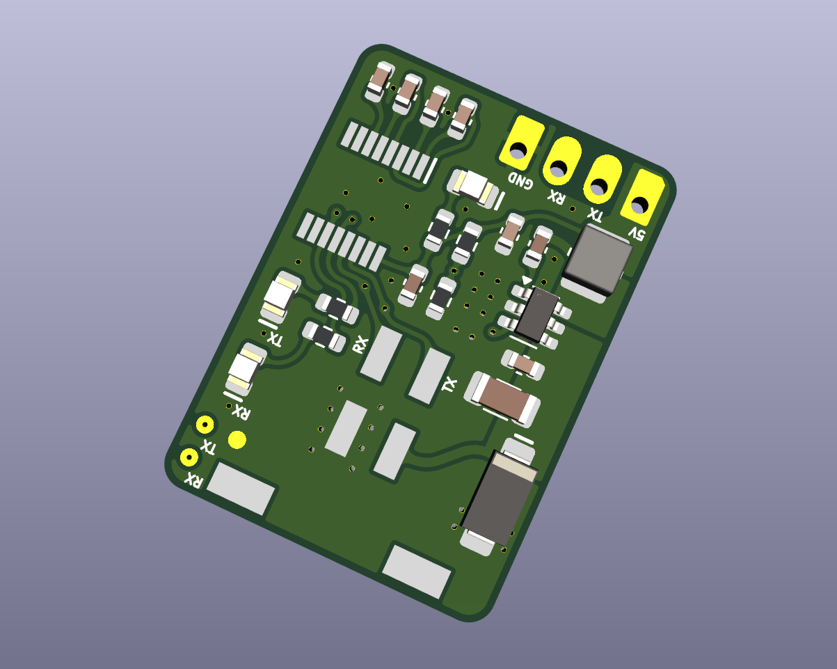
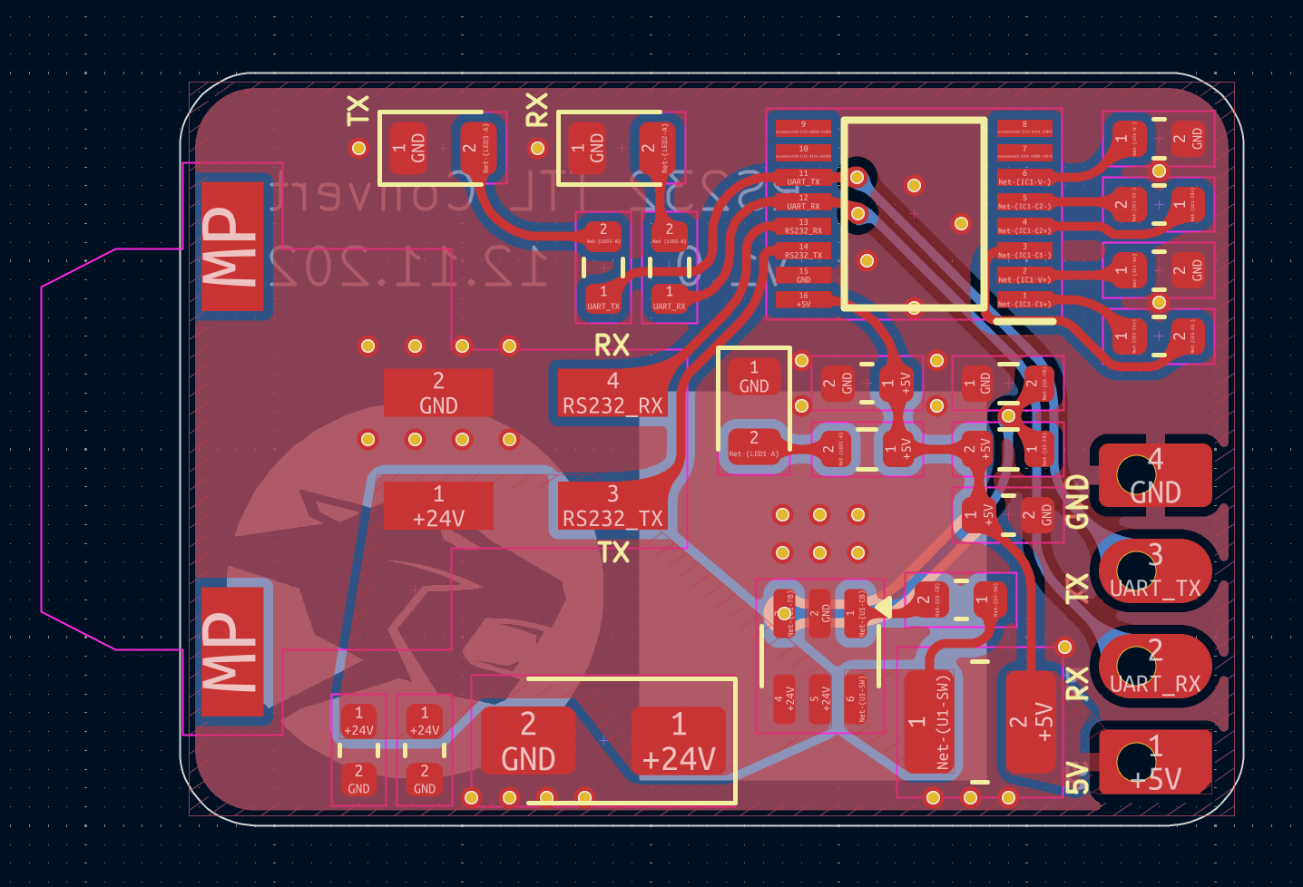
PCB Layout
The layout keeps the main serial paths readable and the connector labels visible, which helps during integration and troubleshooting. Separate pads and headers make it possible to probe the UART lines without disturbing the main harness.
Technologies
KiCad, PCB layout, UART, RS232, TTL logic levels, embedded hardware integration.